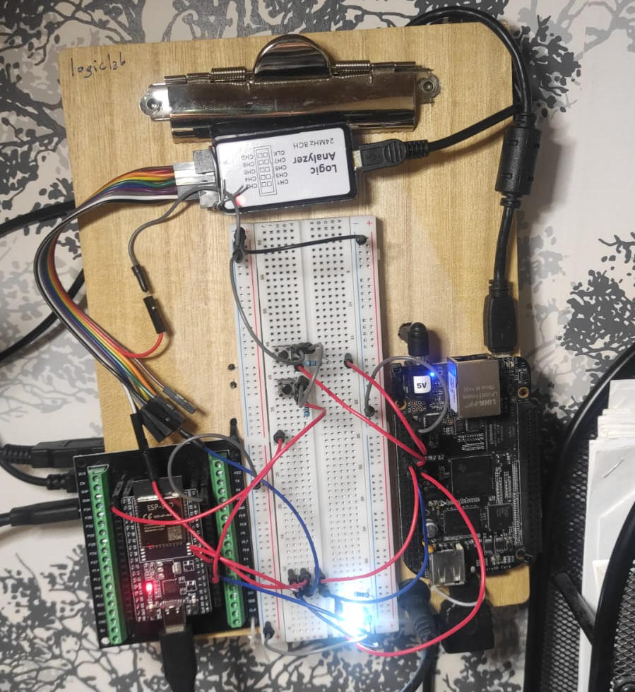
Hardware & Wiring
Connection Table
| ESP32 | → | BBB | Purpose |
|---|---|---|---|
| GPIO17 (TX) | → | P9_13 (RX) | UART data |
| GPIO16 (RX) | → | P9_11 (TX) | UART data |
| GND | → | GND | Common ground — mandatory |
| GPIO4 | → | — | Corrupt checksum button |
| — | → | P9_12 | Corrupt ACK button |
| — | → | P9_14 | LED output |
Single Raw Byte
The starting point: send a single byte over UART with no structure at all. The goal is to see a UART frame on the logic analyzer and understand its anatomy.
Every UART frame follows the same pattern regardless of content: the line sits HIGH (idle), drops to LOW for exactly one bit period (start bit), then the 8 data bits follow LSB first, and finally the line returns HIGH for the stop bit.
0x55 is an ideal test byte (01010101) — bits alternate HIGH and LOW every period, making baud rate verification trivial on the logic analyzer.
#include <Arduino.h>

#define TX_PIN    17
#define RX_PIN    16
#define BAUD_RATE 9600

HardwareSerial MySerial(2);

void setup() {
  MySerial.begin(BAUD_RATE, SERIAL_8N1, RX_PIN, TX_PIN);
}

void loop() {
  MySerial.write(0x55);   // 01010101 — perfect test byte
  MySerial.flush();
  delay(500);
}
Multiple Bytes
Instead of a single byte, we send an array of three bytes back-to-back. On the logic analyzer this produces three consecutive UART frames with a small inter-frame gap between each.
#include <Arduino.h>

#define TX_PIN    17
#define RX_PIN    16
#define BAUD_RATE 115200

HardwareSerial MySerial(2);

uint8_t packet[] = { 0xAA, 0xCB, 0x55 };

void setup() {
  Serial.begin(115200);
  MySerial.begin(BAUD_RATE, SERIAL_8N1, RX_PIN, TX_PIN);
}

void loop() {
  MySerial.write(packet, sizeof(packet));
  MySerial.flush();
  delay(1000);
}
The logic analyzer now shows three frames in sequence: 0xAA, 0xCB, 0x55. Each frame is independent — its own start bit, 8 data bits, and stop bit.
Meaningful Data — ESP32 ↔ BBB
We now assign meaning to each byte. A five-byte frame carries a command from the ESP32 to the BeagleBone Black, which responds with an ACK. The BBB toggles a GPIO LED based on the received command.
Frame Structure
| Byte | Value | Description |
|---|---|---|
| frame[0] | 0xAA | Start byte — marks beginning of frame |
| frame[1] | 0x01 / 0x02 | Command — LED ON or LED OFF |
| frame[2] | 0x00 | Payload length (no payload in this step) |
| frame[3] | XOR | Checksum — XOR of bytes 1 and 2 |
| frame[4] | 0x55 | Stop byte — marks end of frame |
#include <Arduino.h>

#define TX_PIN    17
#define RX_PIN    16
#define BAUD_RATE 115200

HardwareSerial MySerial(2);

const uint8_t START_BYTE  = 0xAA;
const uint8_t END_BYTE    = 0x55;
const uint8_t CMD_LED_ON  = 0x01;
const uint8_t CMD_LED_OFF = 0x02;
const uint8_t CMD_ACK     = 0x10;

uint8_t calcChecksum(uint8_t* data, int len) {
  uint8_t cs = 0;
  for (int i = 0; i < len; i++) cs ^= data[i];
  return cs;
}

void sendCommand(uint8_t cmd) {
  uint8_t frame[5];
  frame[0] = START_BYTE;
  frame[1] = cmd;
  frame[2] = 0x00;
  frame[3] = calcChecksum(&frame[1], 2);
  frame[4] = END_BYTE;
  MySerial.write(frame, 5);
  MySerial.flush();
}

bool readAck() {
  unsigned long t = millis();
  uint8_t buf[16]; int idx = 0;
  while (millis() - t < 500) {
    if (MySerial.available()) {
      uint8_t b = MySerial.read();
      if (b == START_BYTE) idx = 0;
      buf[idx++] = b;
      if (idx >= 5 && buf[idx-1] == END_BYTE)
        if (buf[1] == CMD_ACK) return true;
    }
  }
  return false;
}

void setup() {
  Serial.begin(115200);
  MySerial.begin(BAUD_RATE, SERIAL_8N1, RX_PIN, TX_PIN);
}

void loop() {
  sendCommand(CMD_LED_ON);
  Serial.println(readAck() ? "ACK received!" : "Timeout!");
  delay(2000);
  sendCommand(CMD_LED_OFF);
  Serial.println(readAck() ? "ACK received!" : "Timeout!");
  delay(2000);
}
import serial
import Adafruit_BBIO.GPIO as GPIO

LED_PIN = "P9_14"
GPIO.setup(LED_PIN, GPIO.OUT)
GPIO.output(LED_PIN, GPIO.LOW)

ser = serial.Serial('/dev/ttyO4', baudrate=115200, timeout=1)

START, END       = 0xAA, 0x55
CMD_LED_ON       = 0x01
CMD_LED_OFF      = 0x02
CMD_ACK          = 0x10

def checksum(data):
    cs = 0
    for b in bytearray(data): cs ^= b
    return cs

def send_ack():
    frame = bytearray([START, CMD_ACK, 0x00])
    frame += bytearray([checksum(frame[1:]), END])
    ser.write(bytes(frame))

def read_frame():
    buf = bytearray()
    while True:
        byte = ser.read(1)
        if not byte: return None
        b = ord(byte)
        if b == START: buf = bytearray([b])
        else: buf += bytearray([b])
        if len(buf) >= 5 and buf[-1] == END: return buf

print "BBB ready, listening..."
while True:
    frame = read_frame()
    if frame and len(frame) >= 5:
        if frame[0] == START and frame[-1] == END:
            cmd = frame[1]
            cs  = checksum(frame[1:3])
            if cs == frame[3]:
                if cmd == CMD_LED_ON:
                    GPIO.output(LED_PIN, GPIO.HIGH)
                    print "LED ON"
                elif cmd == CMD_LED_OFF:
                    GPIO.output(LED_PIN, GPIO.LOW)
                    print "LED OFF"
                send_ack()
            else:
                print "Checksum error! Packet rejected."
Error Detection — Checksum Testing
With the protocol working correctly, we verify that the checksum mechanism actually catches errors. Two physical buttons — one on each board — are used to deliberately corrupt outgoing frames.
ESP32 button (GPIO4): When held during a send cycle, the checksum byte is flipped with XOR 0xFF before transmission. The BeagleBone Black receives the frame, recalculates the expected checksum, finds a mismatch, and prints "Checksum error! Packet rejected." — the LED does not change state and no ACK is sent. The ESP32 times out waiting for the ACK and logs "Timeout!"
BBB button (P9_12): When held, the BBB processes the command normally and toggles the LED, but corrupts the ACK checksum before sending it back. The ESP32 receives the ACK frame, verifies its checksum, detects the corruption, and logs "ACK checksum error!"
This two-sided test confirms that both endpoints independently validate every frame they receive — neither blindly trusts incoming data.
Logic Analyzer & Hardware
Waveform captures from PulseView and hardware setup photos.

0x55 (01010101), and the stop bit. The alternating pattern makes bit timing easy to verify by eye.
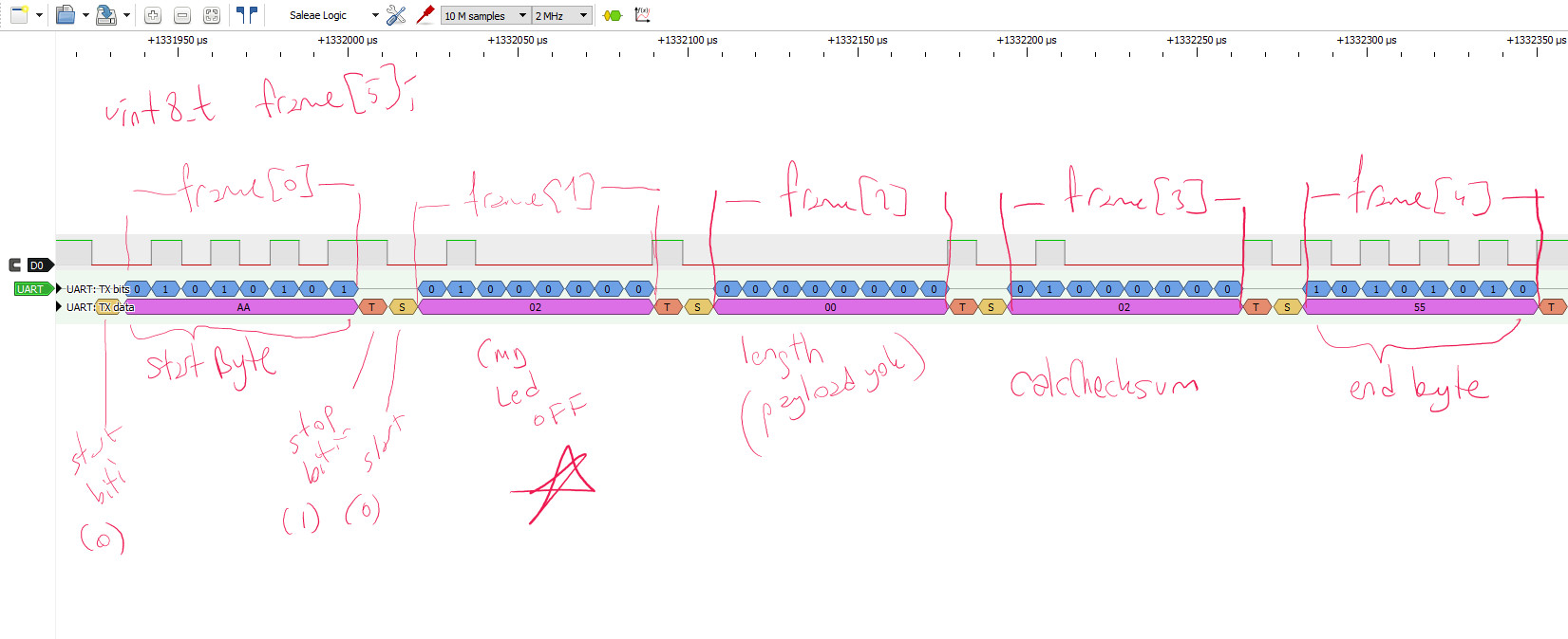
AA 02 00 02 55 — LED OFF commandframe[0] = start byte (0xAA), frame[1] = command (LED OFF), frame[2] = payload length, frame[3] = XOR checksum, frame[4] = end byte (0x55). The hand-written labels show the mapping from code to wire.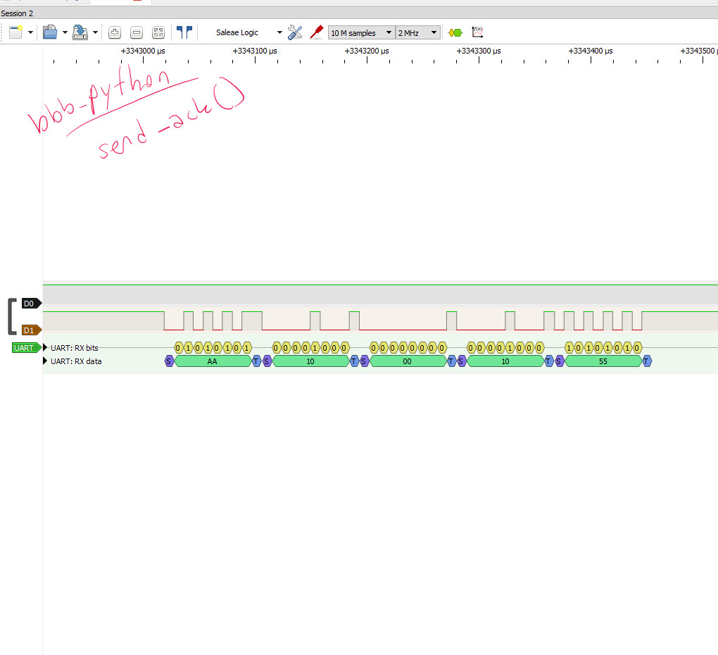
send_ack() — RX channelAA 10 00 10 55) visible on the RX channel (D1). Both TX and RX channels are active — two-way communication confirmed.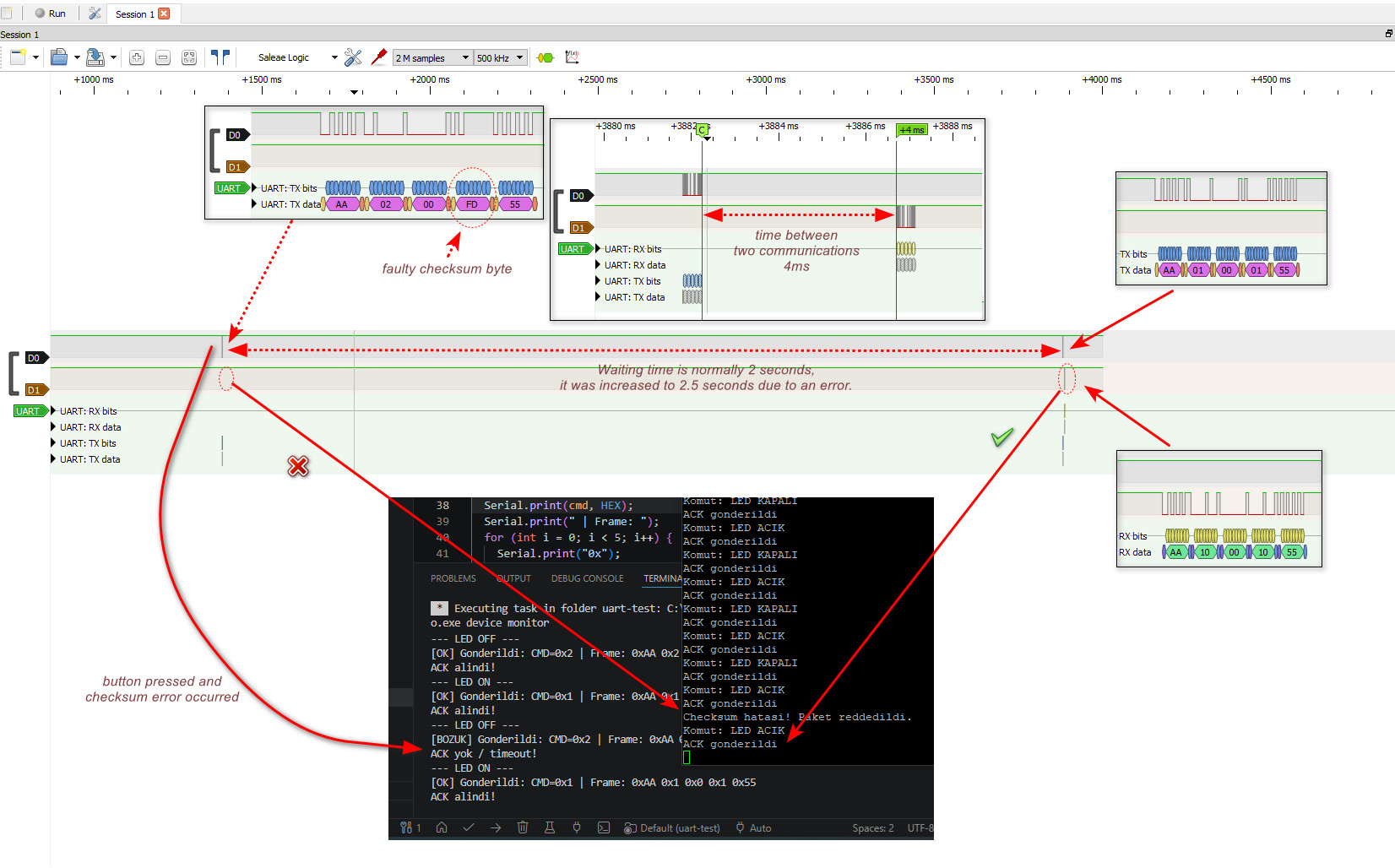
0xFD instead of 0x02. The BBB rejects the frame and sends no ACK; the ESP32 times out. The terminal shows "ACK yok / timeout!" followed by a successful round-trip after the button is released. Inter-frame gap: ~4 ms.