Technical Report · CAN Bus · 2025

CAN Bus Arbitration Experiment
ESP32 & BeagleBone Black

Simultaneous CAN bus frame transmission from two microcontroller boards via SN65HVD230 transceivers, and observation of the protocol-level arbitration mechanism.

ESP32 · TWAI BeagleBone Black · SocketCAN SN65HVD230 · CAN Transceiver Logic Analyzer · 24MHz 8CH 100 kbit/s · CAN 2.0A

Experiment Objective and Scope

This experiment aims to observe the bit-level arbitration mechanism — one of the fundamental features of the CAN (Controller Area Network) protocol — on real hardware. When multiple nodes begin transmitting simultaneously on the CAN bus, the node with the lower ID wins by sending a dominant (0) bit; the node with the higher ID detects that its own recessive (1) bit is being read as dominant (0) on the bus and withdraws. This mechanism operates entirely at the hardware level without any central arbitrator.

CAN Identifiers
NodeID (hex)ID (bin)Role
ESP320x456100 0101 0110Higher ID — loses
BBB0x123001 0010 0011Lower ID — wins

At the first differing bit (bit10): BBB sends dominant (0), ESP32 sends recessive (1) — BBB wins.

Key Parameters
ParameterValue
CAN speed100 kbit/s
Bit time10 µs
Sample point75%
Sample rate2 MHz
TriggerBBB → ESP32 (GPIO15)

Experimental Setup

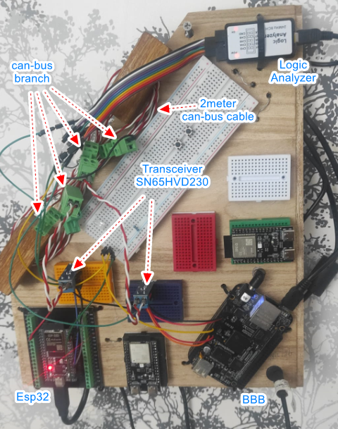
Test hardware - ESP32, BBB, SN65HVD230 transceivers and logic analyzer on the test board
Figure 1. Test board: ESP32 (bottom left), BeagleBone Black (bottom right), two SN65HVD230 transceivers (on breadboard), 2-metre CAN bus cable, and 24MHz 8-channel logic analyzer (top right).
ComponentModel / SpecRole
Microcontroller #1ESP32 (TWAI driver)CAN node — ID 0x456, triggered side
Microcontroller #2BeagleBone Black (SocketCAN)CAN node — ID 0x123, triggering side
TransceiverSN65HVD230 × 2Digital (TTL) ↔ Differential (CAN_H/CAN_L) conversion
CAN cable2 metres, twisted pairPhysical CAN bus line
Termination120Ω × 2 (on-board)Bus impedance: 60Ω
Logic AnalyzerSaleae Logic 24MHz 8CHSignal capture and CAN decoding

Channel Map

D0CAN_L — bus line (primary source for decoder)
D1ESP32 TX (GPIO17)
D2BBB TX (P9.20)
D3Trigger line — BBB P9.15 → ESP32 GPIO15

Experimental Methodology

The core approach is for BBB to both trigger ESP32 and immediately transmit its own CAN frame. The delay between the two nodes' SOF (Start of Frame) moments is controlled by the software sweepDelay parameter on the ESP32 side.

1

Trigger

BBB sends a 50µs HIGH pulse from P9.15 to ESP32's GPIO15. A hardware interrupt (ISR) on the ESP32 captures this rising edge.

2

BBB Frame Transmission

Immediately after the trigger pulse, BBB transmits a frame with ID 0x123 via SocketCAN. Due to kernel network stack latency, this occurs ~250–650µs after the trigger (variable).

3

ESP32 Frame Transmission

After waiting sweepDelay µs from the ISR trigger, the ESP32 sends a frame with ID 0x456 via the TWAI driver. This delay was swept between 100–170µs.

4

Arbitration Window

When the two nodes' SOF moments overlap, arbitration occurs. At the first differing ID bit (bit10), BBB sends dominant (0) and ESP32 sends recessive (1) — BBB wins, ESP32 withdraws.

5

Measurement and Verification

Signals were captured with the logic analyzer; the arb_lost_count (ESP32 TWAI) and arbit-lost (BBB SocketCAN statistics) counters were monitored.

Technical Challenges

Three layered issues were encountered during the experiment, each requiring resolution before the next could be addressed.

Issue 1 — BBB Pinmux: P9.19/P9.20 Boot in I2C Mode ip link show can0 reported UP and ERROR-ACTIVE, yet BBB's TX signal never reached the physical pin.

On Debian 13.5 / Kernel 6.x, P9.19 and P9.20 default to I2C2 mode. The pinmux register value remains 0x30 (GPIO mode, receiver disabled). The system's existing BB-CAN0-00A0.dtbo overlay was added to uEnv.txt as a filename only (no path prefix):

uboot_overlay_addr4=BB-CAN0-00A0.dtbo   # ✓ Correct
uboot_overlay_addr4=/lib/firmware/BB-CAN0-00A0.dtbo   # ✗ Wrong (silent failure)
Issue 2 — Missing SN65HVD230 Bypass Capacitor ESP32 RX error counter exceeded 128 and entered bus-off state.

On one of the breakout boards, the 100nF bypass capacitor (C1, between VCC and GND) had been accidentally removed during rework. This left the 3.3V supply noisy, causing corrupted differential output. A 10nF capacitor was soldered in place to complete testing.

Issue 3 — Extra Termination Resistor (40Ω) When bus impedance dropped to 40Ω instead of 60Ω, signal integrity problems were observed.

Both SN65HVD230 breakout boards already had an on-board 120Ω resistor. Adding one more external resistor connected three in parallel:

120Ω ‖ 120Ω = 60Ω        # ✓ Correct (two boards, on-board resistors sufficient)
120Ω ‖ 120Ω ‖ 120Ω = 40Ω # ✗ Wrong (no external resistor should be added)
Fundamental Challenge — BBB Kernel Jitter BBB's SocketCAN/kernel latency varied between 250–650µs. This ~400µs jitter range is 40× larger than one CAN bit period (10µs at 100kbit/s), making precise software-based timing synchronisation impractical.

Observations and Measurements

PulseView close-up: BBB 0x123 frame decoded, ACK bit visible
Figure 2. PulseView close-up: BBB's 0x123 frame (pink) fully decoded. A short dominant pulse from ESP32 (D1) is visible at the ACK bit — confirming the frame was received correctly. Test points: D0=CAN_L, D1=ESP32-TX, D2=BBB-TX, D3=trigger.
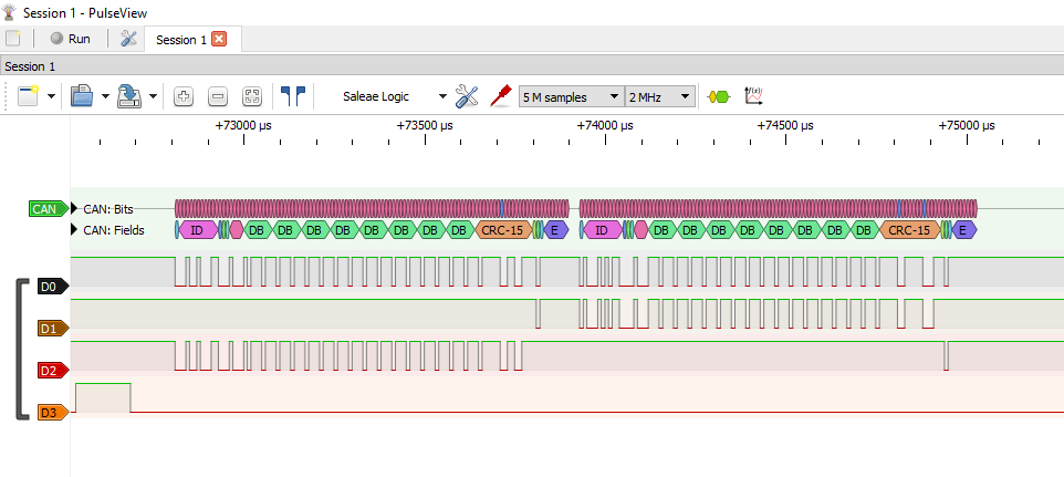
PulseView overview - two sequential frames, ID 0x123 and 0x456
Figure 3. PulseView overview: two frames in sequential transmission. First frame BBB (0x123), second frame ESP32 (0x456). When the bus is busy, the other node waits — sequential communication, no bit-level collision in this capture.

Timing Calibration

Sweep experiments revealed which node transmitted first as a function of sweepDelay:

sweepDelay RangeObservationExplanation
< 135 µsESP32 (0x456) firstESP32 faster than BBB, finds bus busy
~135–140 µsTarget arbitration windowBoth nodes start SOF at nearly the same time
> 140 µsBBB (0x123) firstBBB starts first, ESP32 finds bus busy

Internal Latency Measurements (Marker Analysis)

NodeMarker → Real SOF LatencyJitter
ESP32 (TWAI)~7 µs (very consistent)< 2 µs
BBB (SocketCAN)~73 µs (ortalama)±18 µs
BBB (Absolute latency)250–650 µs~400 µs
Key Finding The ESP32's TWAI driver behaved with high consistency (~7µs, <2µs jitter), while BBB's Linux kernel/SocketCAN stack exhibited ~400µs of jitter — 40× larger than the 10µs CAN bit window.

Evaluation and Next Steps

Deney Sonucu
Partial Success / Bit-level arbitration was not captured

Communication established, protocol verified, timing calibration completed. The primary reason bit-level arbitration could not be captured is BBB's structural kernel latency.

Achieved goals:

Unachieved goal:

Why Was Arbitration Not Captured? BBB's SocketCAN latency varied randomly between 250–650µs on each trigger. With a 100kbit CAN bit period of 10µs, a ±200µs uncertainty made software delay adjustment insufficient. The arbit-lost counter remained zero across 1000 trigger attempts.

Next Step: Experiment with Two ESP32 Boards

When both nodes use the ESP32's TWAI driver, latency will be ~7µs with <2µs jitter. The symmetric latency between the two nodes will allow software-based entry into the arbitration window, and bit-level collision capture becomes a realistic goal.

MethodNode LatencyJitterArbitration Probability
ESP32 + BBB (this experiment)7µs vs 73µs±200µsVery low
ESP32 + ESP32 (next)7µs vs 7µs<2µsHigh
07 — Code and Tools

Software and Development Environment

The experiment consists of two independent programs developed in separate environments: PlatformIO (VSCode extension) for the ESP32, and a direct GCC compiler + PuTTY terminal for the BeagleBone Black.

ESP32 — VSCode + PlatformIO

Written in C++ on the Arduino framework. Uses Espressif's TWAI (Two-Wire Automotive Interface) driver.

# platformio.ini
[env:esp32dev]
platform = espressif32
board    = esp32dev
framework = arduino
monitor_speed = 115200

Upload: → icon in VSCode status bar · Monitor: 🔌 icon

BBB — PuTTY + GCC

Written in C on Debian 13.5. Uses SocketCAN (Linux kernel CAN stack) and the libgpiod library.

# Derleme
gcc -o can_arb_trigger \
    can_arb_trigger.c -lgpiod
echo "Exit: $?"

# Run
sudo ./can_arb_trigger can0

PuTTY → 192.168.7.2:22 · SSH · beagle/beagle

ESP32 Firmware — main.cpp

Receives trigger via hardware interrupt, waits sweepDelay µs, then transmits a TWAI frame with ID 0x456. On each trigger, TX/RX error counters and arb_lost_count are printed to Serial Monitor.

// ── Pin Definitions ────────────────────────────────────────
#define CAN_TX_PIN      GPIO_NUM_17   // SN65HVD230 TXD
#define CAN_RX_PIN      GPIO_NUM_16   // SN65HVD230 RXD
#define TRIGGER_PIN     GPIO_NUM_15   // BBB P9.15 → ESP32
#define MARKER_PIN      GPIO_NUM_4    // D0: timing marker

// ── Sweep Parameters ───────────────────────────────────────
#define DELAY_SWEEP_MIN   100         // µs
#define DELAY_SWEEP_MAX   170         // µs
#define DELAY_SWEEP_STEP  1           // her tetiklemede artar
#define CAN_ID_ESP32      0x456       // higher ID — loses

// ── ISR (Hardware Interrupt) ───────────────────────────────
void IRAM_ATTR onTriggerRising() {
    triggerFlag = true;
    triggerCount++;
}

// ── Main Loop ──────────────────────────────────────────────
void loop() {
    recoverFromBusOffIfNeeded();
    if (!triggerFlag) return;
    triggerFlag = false;

    delayMicroseconds(sweepDelay);    // timing adjustment

    // Marker HIGH → send frame → Marker LOW
    digitalWrite(MARKER_PIN, HIGH);
    twai_message_t msg = {.identifier = CAN_ID_ESP32,
                          .data_length_code = 8, .ss = 1};
    memset(msg.data, 0xEE, 8);
    twai_transmit(&msg, pdMS_TO_TICKS(10));
    digitalWrite(MARKER_PIN, LOW);

    // Advance sweep
    sweepDelay += DELAY_SWEEP_STEP;
    if (sweepDelay > DELAY_SWEEP_MAX) sweepDelay = DELAY_SWEEP_MIN;

    // Report results
    twai_status_info_t status;
    twai_get_status_info(&status);
    Serial.printf("delay=%uus | TX err:%lu | RX err:%lu | arb_lost:%lu\n",
        sweepDelay, status.tx_error_counter,
        status.rx_error_counter, status.arb_lost_count);
}

BBB Trigger Program — can_arb_trigger.c

Sends a trigger pulse from P9.15, then immediately writes a SocketCAN frame with ID 0x123. Reads the arbit-lost counter after each shot; stops when an increase is detected.

// ── Constants ─────────────────────────────────────────────
#define GPIO_CHIP        "/dev/gpiochip0"
#define GPIO_LINE        16    // P9.15 — tetik
#define GPIO_LINE_MARKER 17    // P9.23 — timing marker
#define CAN_ID_BBB       0x123 // lower ID — wins
#define TRIGGER_PULSE_US 50    // pulse width

// ── Main Loop (1000 shots, stop on arbitration) ────────────
while (shot < 1000) {
    shot++;

    // Trigger pulse: HIGH → 50µs → LOW
    gpiod_line_request_set_value(request, GPIO_LINE,
                                 GPIOD_LINE_VALUE_ACTIVE);
    sleep_us(TRIGGER_PULSE_US);
    gpiod_line_request_set_value(request, GPIO_LINE,
                                 GPIOD_LINE_VALUE_INACTIVE);

    // Marker + CAN frame
    gpiod_line_request_set_value(request, GPIO_LINE_MARKER,
                                 GPIOD_LINE_VALUE_ACTIVE);
    write(sock, &frame, sizeof(frame));
    gpiod_line_request_set_value(request, GPIO_LINE_MARKER,
                                 GPIOD_LINE_VALUE_INACTIVE);

    // arbit-lost check
    long current = get_arbit_lost(can_iface);
    if (current > arbit_before) {
        printf("*** ARBITRATION CAPTURED! +%ld ***\n",
               current - arbit_before);
        break;
    }
    sleep_ms(50);
}

CAN Interface Setup — BBB

The ESP32's TWAI driver uses a 75% sample point. BBB's default is 87.5%. A mismatch inflates the RX error counter — both sides must be set identically:

# Configure CAN interface to match ESP32
sudo ip link set can0 down
sudo ip link set can0 type can \
     bitrate 100000 \
     sample-point 0.75 \
     restart-ms 100
sudo ip link set can0 up

# Verify
ip -details link show can0 | grep sample
→ sample-point 0.750  ✓

# Arbitration statistics
ip -details -statistics link show can0 | grep -A1 re-started
→ re-started  bus-errors  arbit-lost  error-warn  error-pass  bus-off